25+ block diagram control system calculator
For representing any system using block diagram it is necessary to find the transfer function of the system which is the ratio of. Tony Roskilly Rikard Mikalsen in Marine Systems Identification Modeling and Control 2015The last chapter showed how systems can be represented in block diagrams.
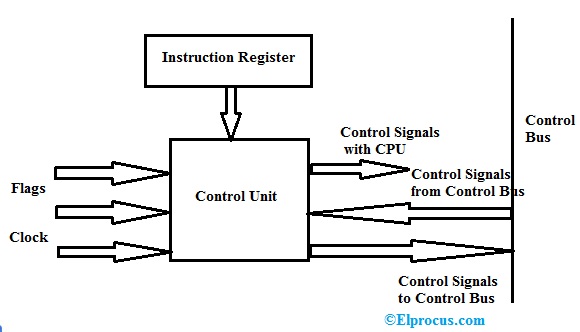
Control Unit Components Function Design And Its Types
Ad Templates Tools To Make Block Diagrams.
. A block diagram is an intuitive way of representing a system. The steps to be followed to draw a block diagram of a system are given below. One of the programs will reduce a complex block diagram of a control system to a simple equivalent forward and feedback transfer function.
Output of this block diagram is - Y S G s R s G s X s Equation 4 Compare Equation 3 and Equation 4 The first term G s R. Identify all the components inputs and outputs. A block diagram is a representation of a system using blocks.
If the order of the resulting polynomial is at least two and any coefficient a iis zero or negative the polynomial has at least one root with. Functional Software Electrical etc. This block diagram is shown in the following figure.
A block diagram is a drawing illustration of a system whose major parts or components are represented by blocks. Draw a block diagram of one of those projects maybe. Step 1 Find the transfer function of block diagram by considering one input at a time and make the remaining inputs as zero.
As well see this is not always the best way to proceed but sometimes it is the. The second series of programs will. If the block diagram is fully specified this technique will always deliver a mathematical model of the system 2.
Step 3 Get the. N1a n1sa n 0 2 where a 06 0 and a n 0. Find Laplace transform of these.
Theres Processor Memory Peripherals - sensors relays indicators Inputoutput Power Etc. Begin by opening a Creately workspace you can make edits to multiple pre-made templates or start creating your block diagram from scratch. Write down the differential equations representing the system.
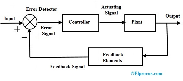
It is a graphical representation that shows us how the systems are interconnected and how the signal flows. These blocks are joined by lines to display the relationship between. Control systems are the methods and models used to understand and regulate the relationship between the inputs and outputs of continuously operating dynamical systems.
Step 2 Repeat step 1 for remaining inputs.
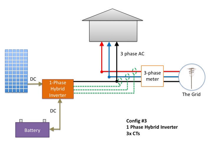
Don T Add Batteries To A 3 Phase Home Before Reading This
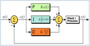
Pid Controller Working Types Advantages Its Applications

Electrical Schematic Diagram For The Control Circuit Of A Forward Reverse Star Wye Delta Motor Co Electrical Circuit Diagram Circuit Diagram Delta Connection
Solved Consider The System Represented By The Block Diagram Of The Following Figure The Closed Loop Transfer Function T S Y S R S Is Select Course Hero
What Is A Computer Block Diagram Quora
What Is A Computer Block Diagram Quora
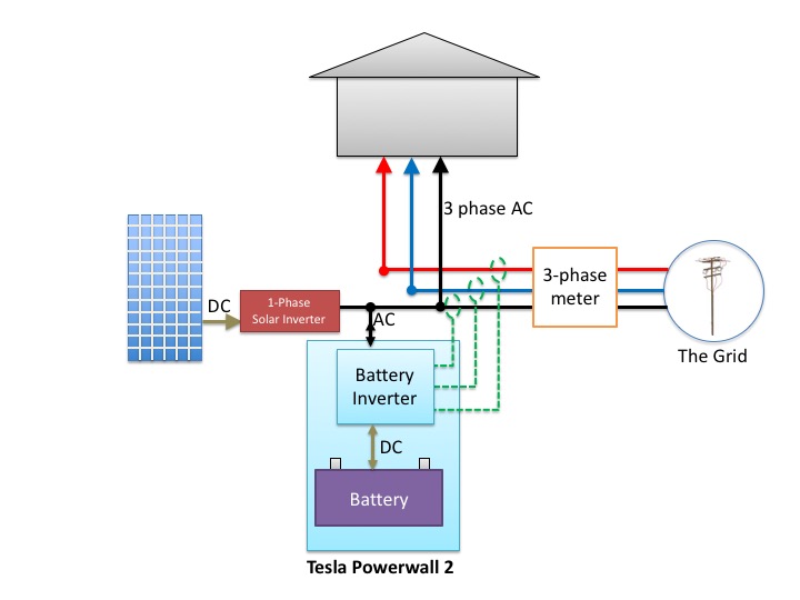
Don T Add Batteries To A 3 Phase Home Before Reading This
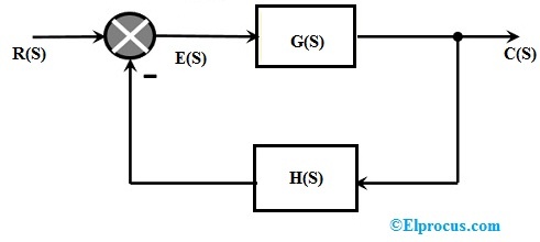
Closed Loop Control System Block Diagram Types Its Applications
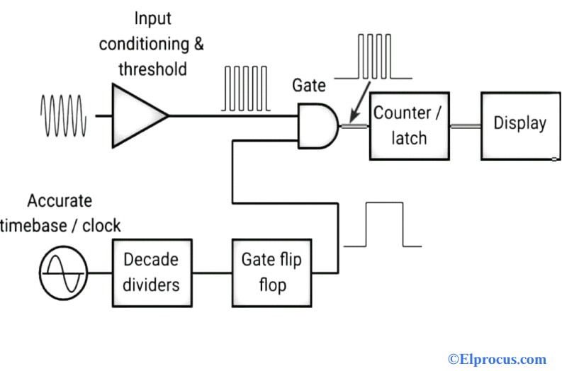
Frequency Counter Block Diagram Circuit Types And Its Applications
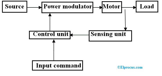
Electric Drive Types Block Diagram Classification And Its Applications
What Is A Computer Block Diagram Quora
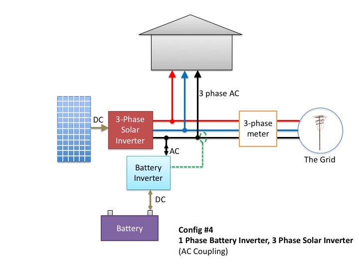
Don T Add Batteries To A 3 Phase Home Before Reading This
Solved Consider The System Represented By The Block Diagram Of The Following Figure The Closed Loop Transfer Function T S Y S R S Is Select Course Hero

Wood Splitter Hydraulic Control Valve System Wood Splitter Log Splitter Hydraulic Systems
Closed Loop Control System Block Diagram Types Its Applications
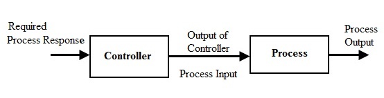
Open Loop Closed Loop Control System And Their Differences
Solved 14 3 2 51 Ti 1 51 X 14 T Al Tso C 2 2 20 0 5 Chegg Com